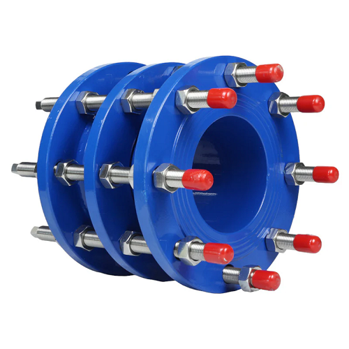
Ductile Iron Dismantling Joints
Dismantling Joints are designed to provide flexibility and ease during the installation, maintenance, or replacement of pipeline components such as valves, pumps, or meters. They allow for axial movement and precise alignment of flanged connections, ensuring a secure and leak-proof assembly.
Dimension: DN 40 – DN 2600
Pressure: PN 10 / PN 16
Material: Ductile Iron EN GJS-500-7 (GGG50)
Standards:
Design: EN 1092-1 – EN 1092-2
How It Works:
These joints consist of a telescopic design with flanged ends and tie rods. The adjustable length allows for easy alignment and connection of pipeline components. Once the desired position is achieved, the tie rods are tightened to lock the joint in place, ensuring stability and preventing separation under pressure.
Advantages:
- Ease of Maintenance: Simplifies the removal and reinstallation of pipeline components, reducing downtime and labor costs.
- Flexibility: Accommodates axial movement and misalignment, ensuring proper fit and connection.
- Leak Prevention: Equipped with gaskets or sealing rings to maintain a tight and leak-free connection.
- Durability: Made from ductile iron, offering excellent strength and corrosion resistance.
Applications:
- Water Supply Systems: Used in pipelines for water distribution and treatment plants.
- Sewage Systems: Facilitates maintenance in wastewater pipelines.
- Industrial Pipelines: Suitable for chemical, oil, and gas industries.
- Pumping Stations: Ensures easy installation and removal of pumps and valves.
- Power Plants: Used in cooling water systems and other critical applications.

Bellows Dismantling Joints
A bellows dismantling joint is a specialized pipe joint designed to facilitate easy assembly and disassembly of pipelines, especially in systems with thermal expansion, vibration, or misalignment. It consists of an expansion bellows (metallic or rubber) integrated with a dismantling joint, allowing for axial movement, angular deflection, and lateral displacement while maintaining a secure, leak-proof connection.
Dimension: DN 50 – DN 2000
Pressure: PN 10 / PN 16
Material: Carbon Steel
Bellows: Stainless Steel
Standards:
Design: EN 1092-1
Advantages
-
Absorbs Movement & Vibration: The bellows component compensates for thermal expansion, misalignment, and vibrations.
-
Easy Maintenance & Replacement: The dismantling joint allows quick removal of valves, pumps, and other pipeline components.
-
Leak-Proof Design: Ensures tight sealing even under pressure.
-
Material Variants: Available in stainless steel, carbon steel, or rubber, depending on application needs.
Applications:
-
Water treatment plants
-
Power plants
-
Industrial piping systems
-
HVAC systems
-
Oil & gas pipelines
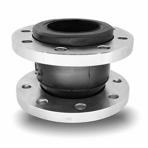
Rubber Expansion Joints
Rubber expansion joints are flexible connectors used in piping systems to absorb movement, reduce vibration, and compensate for thermal expansion or contraction. They help maintain system integrity by preventing stress and damage caused by mechanical or thermal forces. They also isolate vibrations and dampen noise, ensuring smooth operation.
Dimension: DN 32 – DN 600
Pressure: PN 10 / PN 16
Flanges Material: Galvanized Carbon Steel.
Sleeves Material: EPDM + Nylon / NBR + Nylon (Optional)
Standards:
Design: EN 1092-1 – EN 1092-2
Advantages:
- Flexibility: Accommodates pipe misalignment and movement due to temperature changes or mechanical forces.
- Vibration Isolation: Reduces vibration and noise transmission to connected equipment.
- Corrosion Resistance: Made from durable rubber materials that resist chemical and environmental damage.
- Ease of Installation: Lightweight and easy to install, making them suitable for various applications.
Applications:
- Power Plants: Used in steam pipelines and cooling systems to manage thermal expansion.
- HVAC Systems: Isolates vibrations in heating, ventilation, and air conditioning systems.
- Water Treatment: Protects pipelines in water and wastewater treatment plants.
- Chemical Processing: Handles corrosive chemicals and solvents in industrial processes.
- Marine Industry: Used in shipbuilding for condensers, ventilation lines, and sanitary systems.
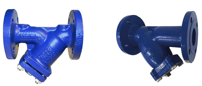
Y-Strainer
A Y strainer is a type of mechanical filter with a mesh or perforated metal straining element used in pipelines to remove unwanted solids from liquids, gases, or steam. It is named for its Y-shaped design, which allows it to be installed in either horizontal or vertical pipelines.
Function
The primary function of a Y strainer is to protect downstream equipment, such as pumps, turbines, spray nozzles, heat exchangers, condensers, steam traps, and meters, from damage caused by debris and solid particles. The strainer captures these particles, ensuring that only clean fluid passes through.
Applications
- Industrial Processes: Used in various industrial applications to protect equipment and maintain process integrity.
- Water Treatment: Ensures clean water by removing particles and contaminants.
- Oil and Gas: Protects pipelines and processing equipment from debris.
- HVAC Systems: Used in heating, ventilation, and air conditioning systems to prevent clogging and damage.
Dimension DN:DN 15 – DN 350
Dimension Inch: 2″ – 12″
Pressure: PN 10 / PN 16
Class 150 , Class 300
Body: Ductile Iron
Carbon Steel / Stainless steel
Standards:
Design: EN 1074-1 / EN 1074-5
ASME B16.34
Flanges: EN 1092-1, EN 1092-2
ASME B16.5
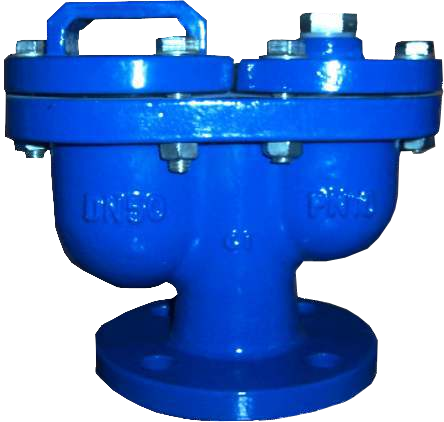
Double Chamber Air Relief Valve
Dimension: DN 40 – DN 300
Pressure: PN 10 / PN 16
Body: Ductile Iron
Ball: Stainless Steel + NBR or EPDM or POLYETHYLENE
Standards:
Design: EN 1074-4
Flanges: EN 1092-2 (ISO 7005-2)
Hydrotest: EN 12266-1 (ISO 5208)
A Double Chamber Air Relief Valve is a specialized type of valve designed to automatically release trapped air or gases from liquid-filled systems, such as pipelines, while preventing the escape of liquid. These valves are critical in maintaining system efficiency, preventing air-related issues like water hammer, corrosion, and reduced flow capacity. The “double chamber” design allows for continuous operation, as one chamber can release air while the other refills, ensuring uninterrupted performance.
How It Works:
- Air Release Mechanism:
- The valve has two chambers, each equipped with a float and a venting mechanism.
- When air enters the valve, the float drops, opening the vent to release the air.
- As air is released, the float rises, closing the vent to prevent liquid from escaping.
- Double Chamber Design:
- While one chamber is releasing air, the other chamber is filling with liquid, ensuring continuous operation without interruption.
- This design allows the valve to handle large volumes of air efficiently.
- Automatic Operation:
- The valve operates automatically based on the presence of air, requiring no manual intervention.
Key Features:
- Continuous Air Release:
- The double chamber design ensures uninterrupted air release, even during high air inflow conditions.
- Compact and Efficient:
- Designed to handle large volumes of air in a compact form factor.
- Durable Construction:
- Made from materials like stainless steel, brass, or corrosion-resistant alloys to withstand harsh environments.
- High-Pressure and High-Temperature Capability:
- Suitable for use in systems with high pressure and temperature conditions.
- Bubble-Tight Seal:
- Prevents liquid leakage while allowing air to escape.
Applications:
- Water Supply Systems: To remove air from pipelines and prevent airlocks.
- Irrigation Systems: To maintain efficient water flow and prevent air-related issues.
- Wastewater Treatment Plants: To release gases like methane and hydrogen sulfide from pipelines.
- Industrial Pipelines: In chemical, oil, and gas industries to ensure smooth operation.
- Heating and Cooling Systems: To remove air from closed-loop systems, improving efficiency.
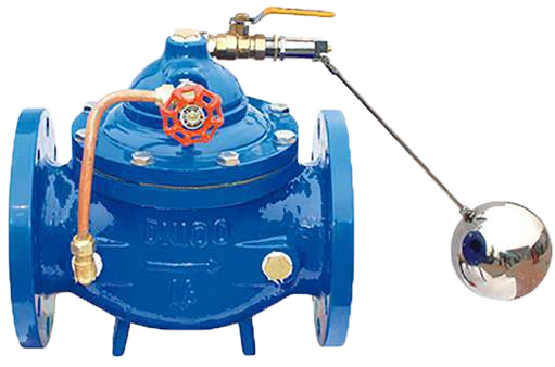
Float Level Control Valve
Dimension: DN 50 – DN 400
Pressure: PN 10 / PN 16
Body: Ductile Iron
Ball: 316 SS
Seat: Brass
Standards:
Design: EN 1074-5
Face to Face: EN 558-1 (ISO 5752)
Flanges: EN 1092-2 (ISO 7005-2)
Hydrotest: EN 12266-1 (ISO 5208)
Float Level Control Valve is a mechanical device used to regulate the level of liquids in tanks, reservoirs, or other containers. It operates based on the principle of buoyancy, where a float rises or falls with the liquid level, mechanically opening or closing the valve to maintain the desired liquid level. These valves are commonly used in water storage tanks, boilers, cooling towers, and other systems where consistent liquid levels are critical.
How It Works:
- Float Mechanism:
- A float, typically made of lightweight and buoyant materials like foam or hollow plastic/metal, is attached to a lever or arm.
- As the liquid level rises, the float rises with it. Conversely, when the liquid level drops, the float descends.
- Valve Operation:
- The float is connected to a valve (usually a globe valve or ball valve) via a lever or linkage.
- When the liquid level reaches the desired height, the float’s upward movement causes the valve to close, stopping the inflow of liquid.
- When the liquid level drops, the float descends, opening the valve to allow more liquid into the tank.
- Adjustability:
- Many float level control valves allow for adjustment of the desired liquid level by changing the length of the lever or the position of the float.
Applications:
- Water Storage Tanks: To maintain consistent water levels in overhead or ground-level tanks.
- Boilers: To control the water level and prevent overfilling or dry running.
- Cooling Towers: To regulate the water level in cooling systems.
- Sewage and Wastewater Treatment: To manage liquid levels in treatment tanks.
- Industrial Processes: In chemical, food, and beverage industries for liquid level control.
- Aquariums and Pools: To maintain water levels automatically.
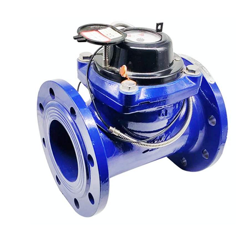
Cold / Hot Water Meter
The Woltman water meter is a specialized device designed for measuring high water flow rates with precision and efficiency.
Dimension: DN 50 – DN 300
Body: Ductile Iron
Flange Connection: ISO 7005-2:1988
Working condition:
Water temperature: 0.1℃~40℃ ( 0.1℃~90℃ for hot water meter).
Water pressure: ≤1Mpa (1.6MPa for special requirement).
How It works:
The Woltman water meter operates using a turbine mechanism. As water flows through the meter, it rotates the turbine blades. The rotational speed of the turbine is directly proportional to the volume of water passing through, allowing for accurate measurement.
Key Features
- High Accuracy: Suitable for measuring large flow rates with minimal error.
- Durable Design: Made from robust materials like cast iron or stainless steel, ensuring longevity and resistance to corrosion.
- Versatile Types: Available in horizontal and vertical configurations to suit different installation needs.
- Low Head Loss: Designed to minimize resistance to water flow.
Applications
- Industrial Use: Ideal for industries with high water consumption, such as manufacturing plants and power generation facilities.
- Agriculture: Widely used in irrigation systems to monitor water usage.
- Municipal Water Supply: Helps in managing water distribution in urban areas.
